More 8×8 LED matrix —
As I mentioned in my previous LED matrix post, there is no need to use 16 Arduino outputs to drive an 8×8 LED matrix when a serial interface and 5 pins could be used. But whilst I’ve got this basic version wired-up then I thought I’d just try using bitmaps and scrolling.
So this is what I did…
Data definitions:
/*
* 8x8 led array bitmaps
* A simple eye that looks left, right and blinks
*/
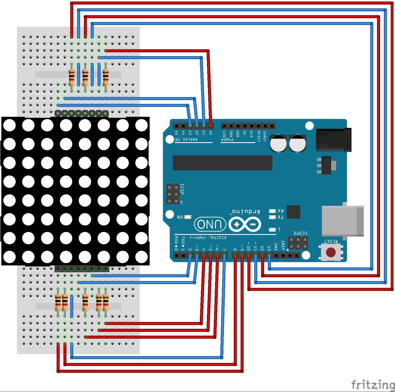
// Arduino pin definitions - (ordered to keep wiring tidy)
int col[] = {14,10,4,12,9,5,8,6}; //columns - driven LOW for on
int row[] = {11,7,3,15,2,13,16,17}; //rows - driven HIGH for on
Although I’m using the same wiring you may notice that I’ve switched the row and column fields and reversed the order of the rows. This is simply to ensure the bitmaps in my following code have the same orientation when displayed on the matrix (in the direction that it is facing me, which is from the left of the above circuit).
This shows that once wired-up the display can be manipulated with code to display in any direction.
// bitmaps of images to display
byte ledBitmap[5][8] = {
  B00101000,              //eye open
  B10111010,
  B01000100,
  B10010010,
  B01000100,
  B00111000,
  B00000000,
  B00000000,

  B00101000,              //look left
  B10111010,
  B01000100,
  B10100010,
  B01000100,
  B00111000,
  B00000000,
  B00000000,

  B00101000,              //look right
  B10111010,
  B01000100,
  B10001010,
  B01000100,
  B00111000,
  B00000000,
  B00000000,

  B00101000,              //eye half open
  B10010010,
  B01101100,
  B11010110,
  B01101100,
  B00010000,
  B00000000,
  B00000000,

  B00101000,              //eye closed
  B10101010,
  B01111100,
  B11111110,
  B01111100,
  B00000000,
  B00000000,
  B00000000,
};
This ledBitmap array holds five crude images of an eye looking in different directions and in two stages of blinking (half-open and closed). They look better on the matrix than as 1’s and 0’s!
Where my previous example inefficiently used a whole int to hold the on/off status of each LED in the matrix, this time I’m being more efficient and using a single bit (1 or 0) per LED.
Setup function:
void setup()
{
  for (int i=0; i<8; i++)        //set arduino pins to be outputs
  {
    pinMode(row[i], OUTPUT);
    pinMode(col[i], OUTPUT);
  }
}
Since my earlier post I’ve discovered that there’s no need to initialise the LEDs by turning them all off. So the setup function is shorter and just needs to set the Arduino pins as outputs.
My bitmap displaying function – ledout :
void ledout(int iBitMapNo, int hOffset, int vOffset, int iDuration)		//Display bitmap number - iBitMapNo
																		//With a horizontal offset of - hOffset
																		//With a vertical offset of - vOffset
																		//Keep the bimap displayed for - iDuration
{
  for (int i=0; i<iDuration; i++)        //repeat image a few times to ensure the eye can see it
  {
    for (int j=0; j<8; j++)              //for each row
    {
      if (j+vOffset>=0 && j+vOffset<8)   //are we within the boundaries of the chosen bitmap
      {
        for (int k=0; k<8; k++)          //set leds in current row according to the bitmap
        {
          digitalWrite(col[k], !bitRead(ledBitmap[iBitMapNo][j+vOffset],k+hOffset));
        }
        digitalWrite(row[j], HIGH);      //display the row, lighting required leds
      }
      delay(2);                          //pause for it to be seen
      digitalWrite(row[j], LOW);         //turn row off again
    }
  }
}
Here I’ve placed all the tricky image display commands into one function. This helps to keep the calling loop function simple and therefore easier to build animations.
The inner loop (subscript k) checks each bit in a line of the selected bitmap to see if the corresponding LED should be turned on or off. This is repeated for each row of the bitmap in the next loop out (subscript j).
The outer loop (subscript i) repeats the display to retain the image on the matrix. Remember, only one line is being displayed at a time so using a sleep command won’t pause the display but, like a raster scan on a TV, repeating the display of all rows will steady the display.
Although not used in this eye example the vertical and horizontal offsets are used to change where the bitmap is displayed on the matrix. Setting both to 1 will display the bitmap one column to the right and one row higher. I’ll add an example using these in a mo.
Loop function:
void loop()
{
  ledout(0,0,0,30);            // Open eye centre
  ledout(1,0,0,30);            // Open eye look left
  ledout(0,0,0,30);            // Open eye centre
  ledout(2,0,0,30);            // Open eye look right
  ledout(0,0,0,30);            // Open eye centre
  ledout(3,0,0,3);             // half-open
  ledout(4,0,0,6);             // closed
  ledout(3,0,0,3);             // half-open
}
With all the tricky code in ledout this loop function is now a fairly straightforward list of which bitmap to display, where to display it (0,0 keeps it central) and how long to keep each bitmap displayed.
As with all Arduino loop functions the sequence is then repeated indefinately.
Pacman example:
// bitmaps of images to display
byte ledBitmap[3][8] = {
  B00000000,              //pacman with mouth nearly closed
  B00111100,
  B01111110,
  B01111110,
  B01111100,
  B01111110,
  B00111100,
  B00000000,

  B00000000,              //pacman with mouth half open
  B00111100,
  B01111110,
  B01111000,
  B01110000,
  B01111110,
  B00111100,
  B00000000,

  B00000000,              //pacman with mouth full open
  B00111100,
  B01111000,
  B01110000,
  B01100000,
  B01111110,
  B00111100,
  B00000000,

};

void loop()
{
  for (int j=-6; j<9; j++)
  {
    if (j%2)
    {
      for (int i=0; i<3; i++) ledout(i,j,0,3);
    }
    else
    {
      for (int i=2; i>=0; i--) ledout(i,j,0,3);
    }
  }
}
Here the the bitmap declarations and loop function of the earlier blinking eye example are replaced. Showing how the same ledout function can be used to display a pacman character that opens and closes it’s moouth as it moves left to right across the matrix.
The outer loop (subscript j) sets the horizontal offset from -6 (off the left side of the matrix) to 9 (off the right side of the matrix). The inner loops (subscript i) alternate between animating an opening mouth or closing mouth as the bitmap is moved right.
Having used ledout to scroll bitmaps of the alphabet in all directions, including diagonally if vertical and horizontal offsets are changed together, I believe I’ve done all that I can with this particular circuit.
Next time I use an LED matrix I’ll use a serial interface and far fewer wires. Possibly with several matrices in sequence?
Categorised as: Electronic Stuff
Comments are disabled on this post