Cumana Electron Floppy Disk Interface —
A mystery circuit board that turned out to be a floppy disk interface for the Acorn Electron (affectionately known as the Elk).
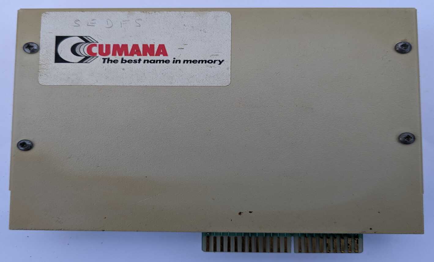
I bought this card for £2 at a radio Hamfest not knowing what it was. It had a “Cumana – The best name in memory” sticker on it and that was enough to convince me it was an add-on for a 1980’s computer, so worth acquiring.
I suspected it may be for a BBC micro, made by Acorn, but from it’s shape I eventually realised it was a plug-in for another Acorn computer, the Electron.
At this point I nearly gave up on it. I didn’t have an Electron and having a couple of BBC computers I didn’t think it worthwhile to get their cheaper cut-down relative (how wrong was I to look down my nose at the Elk!).
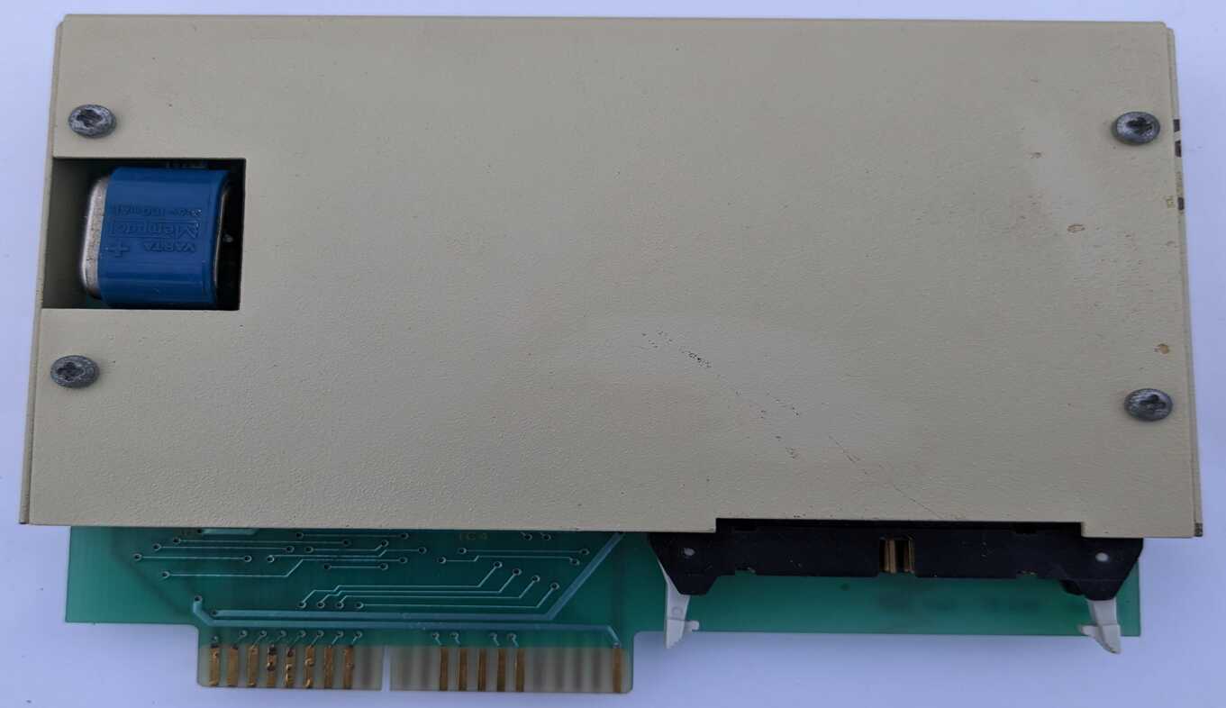
But this interface card, encased in a sturdy metal enclosure, had a cut-out with something blue poking out. I realised this was a battery that would leak, if it hadn’t already, and I couldn’t leave any circuit board to that fate.
A couple of months later, an Electron purchase along the way, and I’ve enjoyed exploring this little card.
Battery Leak
The biggest danger to old electronics (after land-fill) is batteries (and electrolytic capacitors which are a similar hazard).
As these components age the chemicals they contain can burst out and leak across circuit boards. Destroying PCB traces and other components that the leaking electrolyte comes into contact with.
This electrolyte isn’t super corrosive but leave it on a PCB for months or years and it will have time to react with anything metal that it touches.
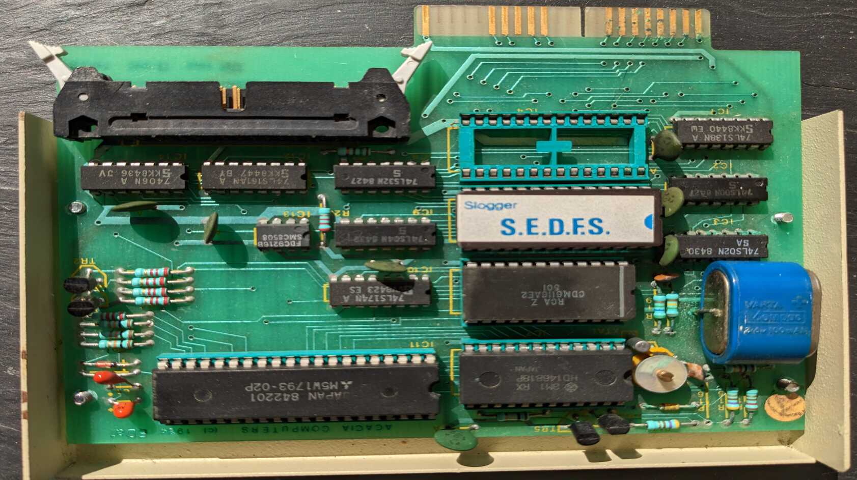
I was lucky. This blue Varta Mempac battery had leaked but the corrosion wasn’t too bad and the board was salvageable.
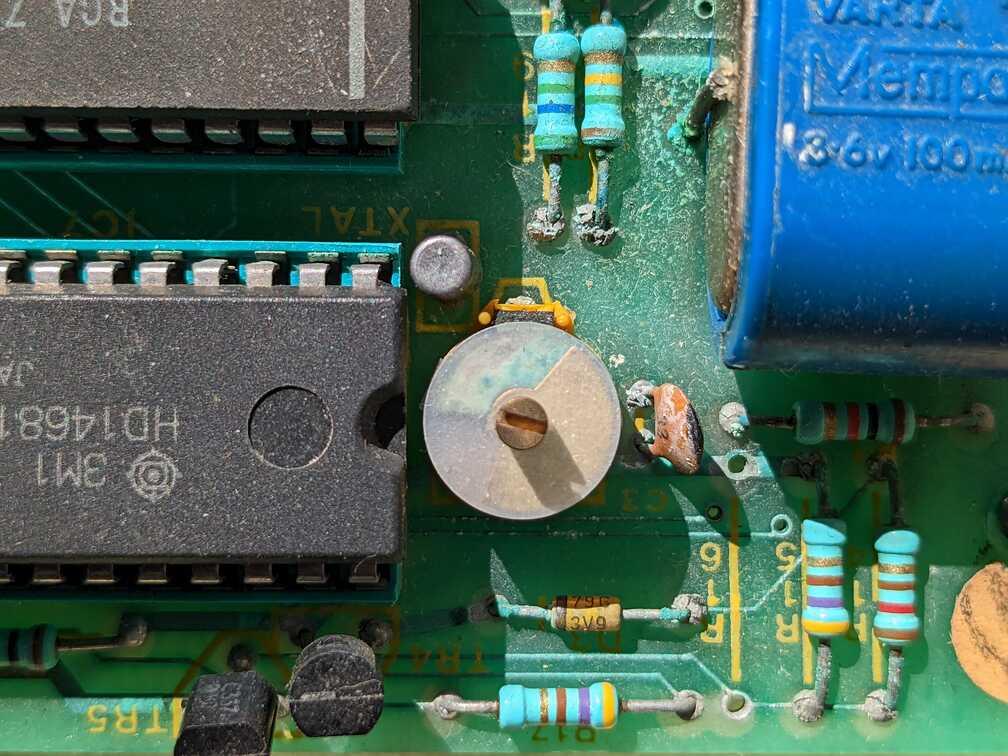
The board looked fine at arms length but zoom in and you can see the corrosion on all the component legs in this photo. Fortunately no traces were eaten through but the trimmer capacitor in the centre was a write-off.
First task was to remove and dispose of the battery. No need to de-solder, I just cut its legs.
I’m not replacing the battery at this stage. The card may work fine without it? Well, it will warn that the battery needs replacing and require the date and time setting every time I use it but that won’t annoy me unless I plan to use it a lot.
Should I need to replace the battery then I’d try a coin cell holder (there is room). But ensuring the battery is protected from the reverse re-charging voltage with a diode.
Next the leaked battery ‘acid’ needed to be deactivated. As the electrolyte isn’t really acid but a caustic alkali then the best solution is to actually cover it with a mild acid! I used distilled vinegar but lemon juice is also suitable. There’s no violent reaction, just some mild fizzing and bubbling as the acid and akali mix.
After a few minutes the board then needs washing. Don’t be afraid to use water but make sure it is thoroughly dry before powering up or even putting into storage.
Gentle scrubbing with an old toothbrush helped to remove most of the crusty deposits around component legs.
I live in a hard water area, so tap water can result in some residue staining on a board. Some isopropyl alcohol was therefore used to mop the board clean.
The end result isn’t perfect. Affected solder joints have a dull dry look to them and the only way to fix that is to reheat with a soldering iron and apply some fresh solder.
Unfortunately my cleaning process also removed some of the silkscreen printing from the board! Had I realised then I would have been gentler with the toothbrush. Something to watch out for. Always best to take lots of photos before you start.
If corrosion appears to have spread underneath any ICs then they are best removed and replaced after a thorough clean-up. But de-soldering introduces the additional risk of lifting traces from the board and so causing further damage.
I had one IC affected in this way but I’ve left it alone for now. I’m sure I’ve managed to deactivate all the corrosive electrolyte and if not then it’s only a common 74LS02, so easily replaceable. I’ve also taken care to map out all the traces around and under it.
I mentioned that a variable ‘trimmer’ capacitor was a write-off. The corrosion had worked its way up through the plates of the component so all were blue-green and instead of being air-gapped the plates were shorted.
This capacitor is close to a quartz crystal and IC7 (HD146818) a Real Time Clock. Checking the data sheet for this RTC there is fortunately a sample timing circuit that suggests this trimmer cap should be 15pF. So I’d suggest a replacement with a 2 to 30pF range should be adequate. It’s easily replaced but an oscilloscope or frequency meter will be needed to ensure the repaired board is tuned to give a clear 32.768kHz clock signal to the RTC.
The card-edge connectors on this PCB were dull with some blue-green corrosion to the copper fingers. After cleaning them with vinegar and water I gently rubbed them with a fibre-glass pen to get them all shining again.
Reverse Engineering
Wanting to know if the battery leak had damaged any PCB traces, I used a multimeter to ‘beep out’ circuits to check they were still conducting and not shorting to other traces.
As I kept track of these tests a circuit schematic started to take shape, so I recorded that into KiCad and tidied the initial mess into a full schematic diagram.
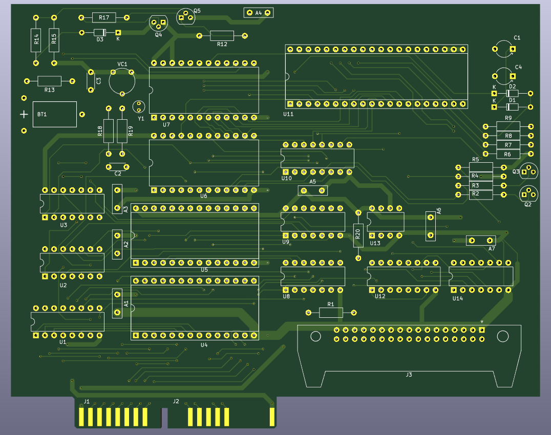
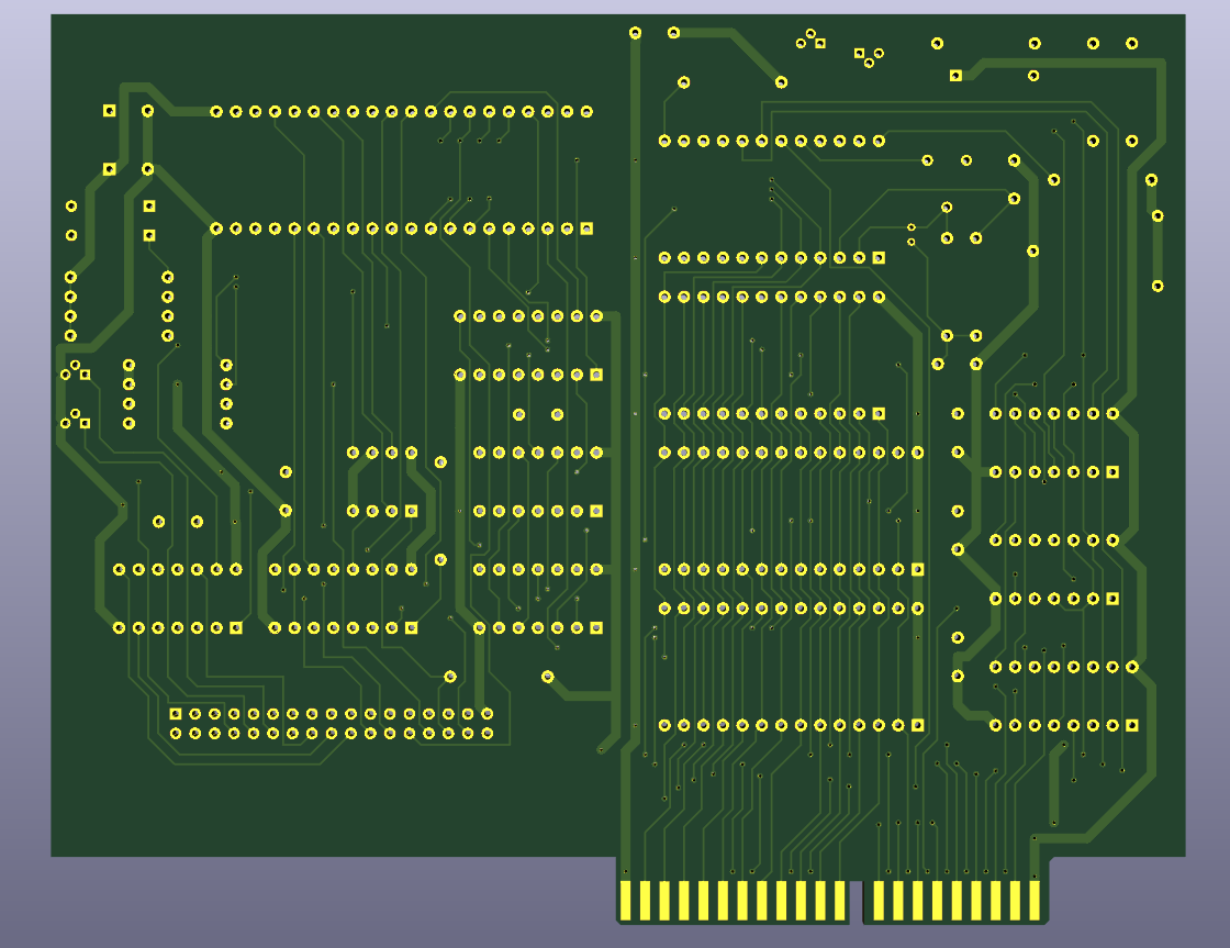
Wanting to exercise my KiCad skills further (it’s been a while) I then started to build a replica PCB. This isn’t a precise copy but components are in the same places and all traces follow the same routes. The end result is the same size as the original and importantly the edge connectors are the right size and in the right place.
I hope the schematic and PCB layout will prove useful to anyone who has suffered greater battery damage and needs to identify and repair broken traces or replace damaged components.
Interface Design
I can’t help thinking that the metal enclosure for this interface card was an unnecessary cost compared to a plastic alternative. Adverts at the time described it as a “hard wearing BBC beige cabinet”. Maybe the added weight suggested something of greater value but it would spend its life plugged into a plastic computer.
The square cut-out in the case to allow the battery to slightly poke out also suggests an unfortunate design choice that added construction cost.
But the card itself is well laid out and is a great example of just how accessible and comprehendible the electronics of that era were.
All the larger ICs on the PCB are socketed (extra cost but appreciated).
IC4 & 5 are the 28-pin ROM sockets (see below).
IC6 is a 24-pin CDM6116 (CMOS 2048-word by 8-Bit LSI Static RAM i.e. 2kB) used for buffering and to ensure the interface does not deplete available Electron memory.
IC7 is the 24-pin Real Time Clock (HD146818) that requires the battery.
IC11 is the large 40-pin Mitsubishi M5W1793 disc controller. This is being clocked at 1MHz so this interface is configured for mini-drives (5.25″ or 3.5″ disks). A 2MHz clock would enable this IC to interface with 8″ disks.
Other ICs are soldered to the PCB and are all TTL logic chips other than IC13 an FDC9216B which is an 8-pin Floppy Disk Data Separator (FDDS). It’s this IC that takes the stream of signals read from a disk and separates the data from the clock signal. The B in the IC name suggests it’s ok with 5.25″ and 8″ disks but the 4MHz clock and Single/Double Density options mean this interface is configured for 5.25″ disks.
The speed of reading from 5.25″ floppies was approx 250kbit/s.
ROMs
The interface card has 2 sockets for ‘sideways’ ROMs marked as IC4 and IC5 on the board (U4 and U5 on my schematic). The disk filing system ROM was in IC5 and IC4 is available for further expansion (word processor, game, etc).
My single EPROM is a Texas Instruments TMS 27128JL-25 (16384 word by 8-bit or 16kB) but it doesn’t contain the Cumana Disk Filing System. Instead it contains the Slogger Electron Disk Filing System (SEDFS). This must have been a later upgrade and explains why the Cumana sticker on the front of this interface has SEDFS pencilled on it. The Cumana DFS doesn’t appear to have been popular. One limitation was a directory depth of only 1 and another was that it needed utilities provided on a separate floppy disk. SEDFS is supposedly a compatible replacement with better features and performance. Including those utilities to format disks, etc.. being included in the ROM.
A download of this ROM showed it to be V1.00 from 1986 by Slogger Ltd.
For the download I used my TL866II+ and the minipro package for Linux. The exact TI chip wasn’t listed in minipro but the following worked:
minipro -p CAT27128A@DIP28 -r SEDFS.hex
Out of curiosity for the 6502 assembly language I then spent some time disassembling the ROM contents. This was really interesting but after several evenings of slow progress I calculated that I’d only decoded 3% of the ROM. So I realised this was a rabbit-hole that I didn’t currently have the time to go down.
My preferred manual disassembly method is to use a spreadsheet to provide some automated decoding of instructions whilst allowing me to add copious comments. I find it more informative to slowly uncover the code (it’s like software archaeology!) as this aids my understanding of the code as I progress.
Alongside this painstaking method I also used dxa. This is a 6502 disassembler that complements xa, a 6502 cross-assembler which works well on Linux.
dxa is still under construction but made quicker progress with decoding the ROM. It didn’t complete the job though as it relies on you to identify areas that are not code to progress a bit further each time.
My dxa command is below with references to a file of data blocks to ignore and a file of labels to substitute for some of the key addresses used (both files are a work in progress).
dxa -N -a enabled -g 8000 -d strict -B SEDFS.data-blocks -l SEDFS.labels -E SEDFS.hex > SEDFS.asm
This 6502 disassembly is a topic I’d like to return to one day. My limited progress only uncovered some of the Electron ROM Filing System (RFS) showing how any ROM should identify itself and responded to common Electron ROM commands. I’d like to progress further to better understand how SEDFS commands control this interface card to transfer data between disk and Electron.
Further Research
I didn’t find much about this interface card online, which prompted me to publish my schematic and PCB layout.
A 1985 Cumana advert offered this Electron disk interface for £115.95. Yet the same advert also listed their BBC disk interface (which didn’t include an RTC or metal case) for £79.95.
Interestingly it’s delivered in re-usable packaging. Why? So you could send it back for battery replacements! When the battery gets low a “WARNING! – Battery Broken” message is displayed. So I’ll have to see how it behaves without any battery.
You could also send it back to have additional ROMs fitted but I couldn’t find a price for these services.
The interface is compatible with 5.25″ and 3.5″ floppy disk drives, single and double density disks (actually not quite double but 1.8 times the storage), 40/80 track and single/double-sided drives. It can address two drives provided they’re sharing the same ribbon cable (see FDD-Select0 and FDD-Select1 on the schematic).
The following sites were useful sources of Electron hardware manuals
https://stardot.org.uk/
http://8bs.com/othrdnld/manuals/hardwareelectron.shtml
Both sides of the interface card are etched with “ACACIA COMPUTERS 1984 ALW EDa1 iss D” and a serial number is lightly scratched by hand on the surface “85052473” (did they really do that on every card by hand?). IC date codes range from mid-1984 to the 8th week of 1985 and that serial number suggests manufacture in May 1985?
Sadly the original Cumana Ltd, Acacia Computers Ltd and Slogger Ltd have all since ceased trading.
Despite a recent impulse purchase of an Acorn Electron I still can’t use this interface card. The card is designed to plug into an Electron expansion unit such as the Acorn Plus-1 or an alternative such as the Rombox Plus from Slogger. I shall keep an eye out for an affordable one or look into the possibility of making my own connection solution to the Electron in the meantime.
My schematic, replica PCB design, bill of materials and the SEDFS ROM can all be found on my GitHub Silicon Heaven repository: https://github.com/agben/Silicon-Heaven
Categorised as: Silicon Heaven
Comments are disabled on this post