Blinkenlights Plug-in —
Making an LED blinkenlights plug-in for monitoring 8-bit digital circuits.
Why?:
In my previous 8-bit CPU registers post I mentioned my concern about hard-wiring LEDs onto the CPU circuit boards. Whereas providing a series of 9-pin male headers offered more versatility: test points for a logic analyser, connection points for a console display, connection points for feeding signals into the circuit, could be left empty without affecting CPU performance or, if I wanted lots of blinkenlights, an LED plug-in could be added.
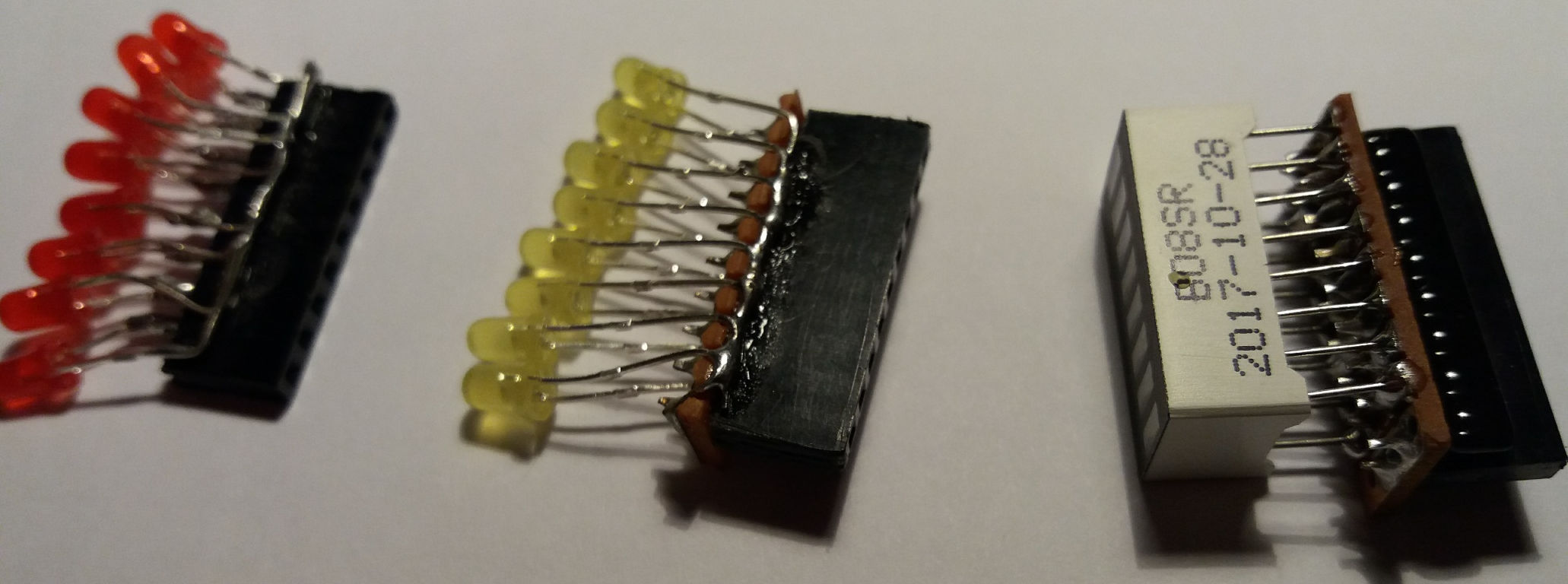
Below are some of my early attempts at making 8-bit blinkenlights plug-ins. The right-hand version with the LED bargraph display being the neatest and most robust when plugging in/out of circuits. As I needed to make some more I thought I’d document the process.
Parts List:

10x25mm stripboard PCB (9 rows of 4 hole copper strips)
9-pin	female header socket
330r	9-pin commoned resistor array (i.e. all 8 resistors connect to the 9th pin)
8 segment LED bargraph display in a 16-pin DIL module (dual in line)
Preparing the stripboard:
I cut-down some stripboard (a.k.a. Veroboard) offcuts to 4×9 hole pieces. I use a craft knife to score a groove between the copper strips and then snap the boards to size. To cut across the copper strips I first use a drill bit to enlarge a row of holes (as you would to make breaks in a copper strip) and then score with a knife and snap to size.
Because I’m using old offcuts the copper strips had oxidised so I gave them a rub with some fine abrasive paper to brighten them up. This isn’t for show but to ensure solder takes to the strips and forms a good contact.
Next I cut eight of the copper strips leaving the ninth intact. Or cut all nine and solder the ninth back together, whichever is easier. Cutting these strips between the holes is fiddly. Usually you would make a break by enlarging one of the holes but I wanted to keep the boards small (4×9). A larger (5×9) board would obscure more of the circuit board it will be plugged onto.
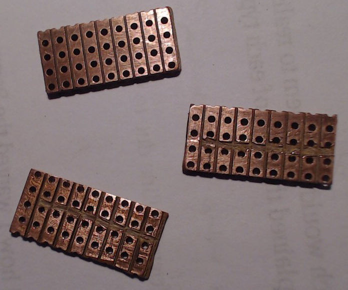
The picture below shows three of these boards, the bottom two with their copper strips cut down the middle. These mid-board grooves don’t look very neat but they test ok (i.e. no short-circuits between the remaining strips). I used a craft knife to make the cuts, tidied any remaining burrs with a small file and brushed them clean with an old toothbrush.
Under Side:
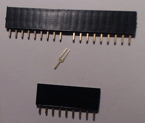
To connect to the male header pins on each CPU circuit board I need a row of nine female header sockets on my plug-in. These come in longer strips but are easily cut-down to size. Count the number of sockets needed and then pull out the next pin from the bottom of the socket with some long-nosed pliers. Then use a craft knife to score both sides of the header before snapping off the required nine socket segment.
The 9-pin header is then soldered across the width of our 5×9 plug-in board on one of the middle rows next to the mid-board groove that was cut earlier. Try and get the header sockets at right angles to the plug-in board, so when it’s plugged in the board will be flat.
On the other side of the mid-board groove we need to solder the resistor array. This 9-pin SIL (single in line) package will have a marker to show the common pin that all 8 resistors connect to. If not use a multimeter to work out which of the end pins it is (resistance will measure 330r from it to each of the other 8 pins). This ‘common’ end must be soldered to the end of our plug-in board that doesn’t have a groove cut in its copper strip. The picture below shows two plug-in boards with soldered resistors and a third with a white dot to show the common end of the resistor array.
Top Side:
With the header sockets facing down and the soldered copper strips facing up (yes, the plug-in stripboards are used upside-down), I can now add the LED display. Before doing this I tested the LED bargraph module in a breadboard with a resistor array to a) check all the LEDs were ok and b) confirm which end is the anode (+) and which is the cathode (-). I don’t want to complete soldering of the 16-pins before finding I have it the wrong way around or that any of the LEDs are faulty.
The LED array slots into the copper strip side of the plug-in board but is not pushed fully into the board. The 16 pins just need to be inserted enough to hold them in place whilst they are soldered to each copper strip on the board. Having long legs on the LED bargraph module helps but I also use some clamping tweezers as a heat sink and keep the soldering hot but quick, so as not to damage the LEDs.
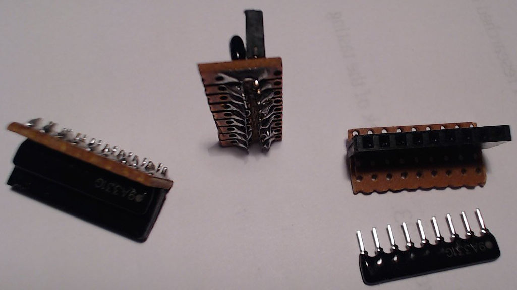
Below are three of these plug-in boards shown from different angles. Note the LED array pins not going fully through the stripboard to enable them to be soldered from above (well actually from the side)

Here we have my 8-bit CPU registers board working fine without any blinkenlights plugged into the four rows of red 9-pin headers (one for each register and one on the left for the data bus.

But how do we know if the CPU registers are working correctly? Well here’s the same board with four blinkenlights plug-ins attached to display register and bus contents during CPU operation.

These blinkenlights are trivial optional extras to an 8-bit system but they’re a great help to show how it works.
Update: With the addition of a 5V pin on the CPU circuit boards an alternative Blinken Hex Light plug-in can be used to display data values in hexadecimal rather than binary format.
Categorised as: Electronic Stuff | Homebrew 8-Bit CPU
Comments are disabled on this post