8×8 LED Matrix —
For some variety I thought I’d add an electronics post to this website. This isn’t really a complete project but more of a hacking session with an 8×8 LED matrix.
Taking time to understand and experiment with even such a basic component is a useful way of learning tricks that can be incorporated into future projects. Finding your own way can also be a rewarding challenge and what you discover tends to stick in your memory better than if you’d just read about it.
So this is what I did…
8×8 LED Matrix:
I’m using a cheap (<£1) 8 by 8 array of LEDs in a package with 16 pins. The model number printed on the side reads 1088AS and a search on that will provide a basic schematic that shows what the pins are for.
Rows 1 to 8 are connected to the matrix pins: 9, 14, 8, 12, 1, 7, 2, 5
and columns 1 to 8 are connected to matrix pins: 13, 3, 4, 10, 6, 11, 15, 16
Other 8×8 matrices are available but they’re either more expensive (multi-colour), which I wouldn’t want to risk with my mediocre electronic skills, or they’re more complex (serial interfaces), which I may tackle in a future post.
In fact the variety of types is surprising but what’s more surprising is that they all appear to have different pin-outs.
My 16 pin matrix provides connectivity to each of the 8 rows and 8 columns. By driving a row LOW (0v) and a column HIGH (5v) the corresponding LED on the matrix (where that row and that column cross) will be lit. So I started by getting a single light to move around the matrix and it all appeared to be easy. I then realised that getting more than one LED lit at a time would be far more difficult.
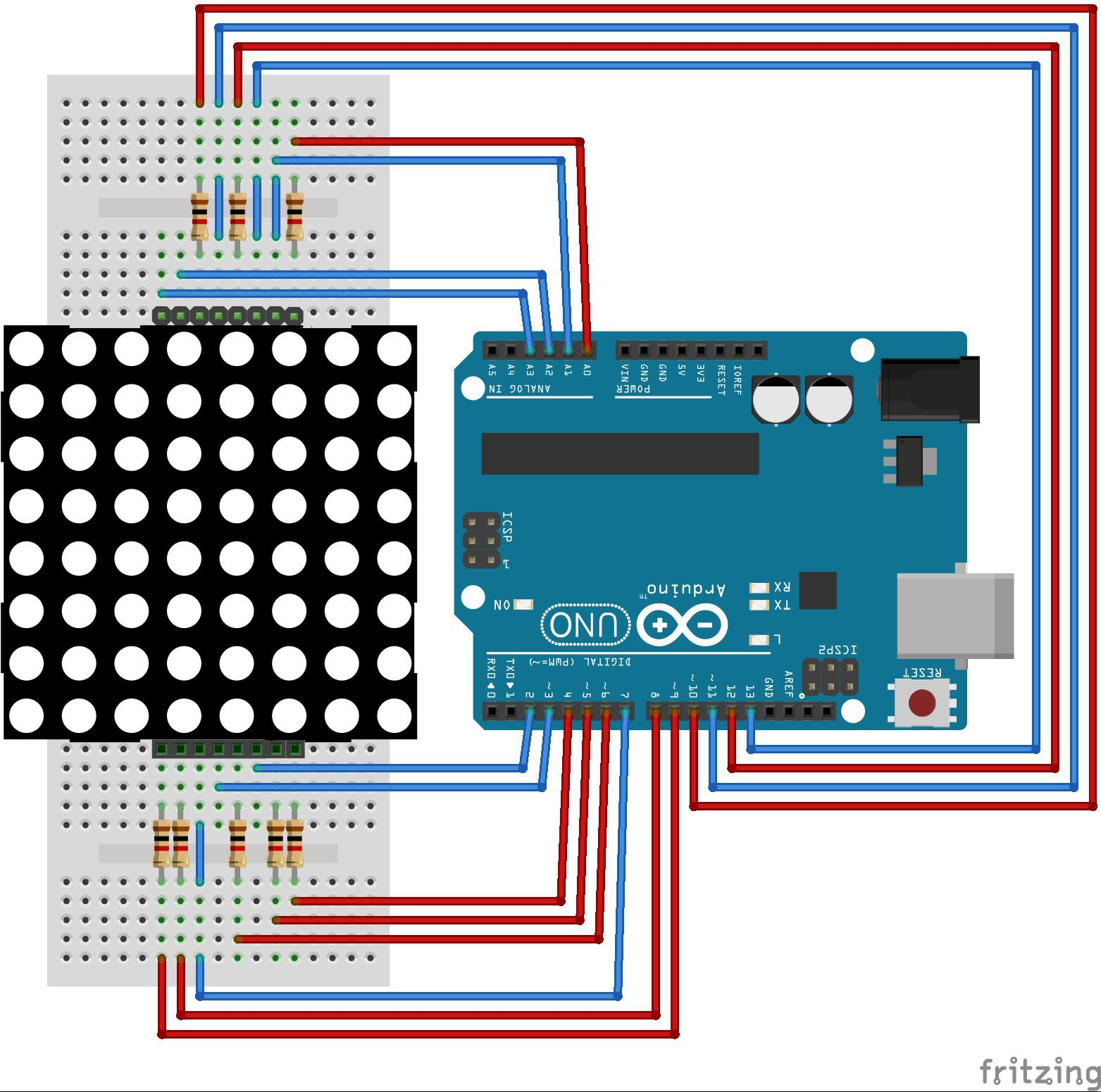
But first, this is how I wired up my matrix to an Arduino.
The Circuit:
To get the pin orientation of the matrix look at the labelled edge. The pins on that side are 1-8 and they’re 16-9 on the far side. As per normal DIL packages the lowest pin is opposite the highest pin.
To protect the LEDs I put a 1k resistor onto each row pin. Thereby ensuring a resistor in each circuit (between Arduino pin, via LED and resistor, and back to Arduino).
That left 16 connections to make to the Arduino pins D2 to D17 (D14 to D17 are labelled A0 to A3). Which wires connect to which digital port isn’t actually that important because the following code can be adjusted to cater for any order. What is important is to note which wires connect to matrix rows (via a resistor) and which to matrix columns. So two different colours of wire would be a help.
I’ve chosen a connection order that looks neat on this circuit picture but I could equally have used D2-D9 for rows and D10-D17 for columns.
The Code:
To start with I had a single light moving around the perimeter of the matrix. But that was too simple so I added a variable length ‘tail’ of lights to follow it.
The code starts by declaring the sequence of Arduino pins that connect to each row and each column.
Then some variables to set the length of the tail (1 for a single light and up to 28 for the whole perimeter), an array holding the number of each LED in the tail and a counter to show which one is the leading LED.
/*
 * 8x8 LED array test1
 * display a line of lights moving around the perimeter of the 8x8 matrix
 */

// Arduino pin definitions - (ordered to keep wiring tidy)
int row[] = {14,10,4,12,9,5,8,6};    //rows - driven LOW for on
int col[] = {17,16,13,2,15,3,7,11};  //columns - driven HIGH for on

// give our moving light a tail?
int tailLen = 10;      //choose 1 to 28 to set length of tail
int tail[28];          //number of each led currently being lit
int tailPos = 0;      //current position on leading light

int i, j;		//general counters
The setup function sets each of our row and column pins as digital outputs. Makes sure all LEDs are turned off before we start and initialises the tail array.
void setup()
{
  for (i=0; i<8; i++) 				 //set arduino pins to be outputs
  {
    pinMode(row[i], OUTPUT);
    pinMode(col[i], OUTPUT);
  }
  for (i=0; i<8; i++) 	             //clear
  {
    digitalWrite(row[i], HIGH);
    digitalWrite(col[i], LOW);
  }
  for (i=0; i<=tailLen; i++) 		  //initialise the tail
  {
    tail[i]=-1;
  }
}
The loop function traces the outline of the 8×8 matrix simply by running through a series of loops to identify which pin to turn on. The function ledout() will deal with turning the LEDs off and on. That way I could modify the loop function to display different patterns without having to change the digital output commands.
You’ll notice that I’m addressing each LED in the matrix as a number between 0 and 63.
void loop()
{
    for (i=0; i<8; i++)
    {
      ledout(i);
    }
    for (i=15; i<56; i=i+8)
    {
      ledout(i);
    }
    for (i=63; i>55; i--)
    {
      ledout(i);
    }
    for (i=48; i>0; i=i-8)
    {
      ledout(i);
    }
}
The ledout function adds the new LED to the tail array and in doing so will erase the end of the tail.
It then loops through the tail array and converts each LED number into a row and column number. Dividing by 8 to get the column (quotient) and using the remainder (modulus) when dividing by 8 to get the row.
void ledout(int i)
{
  tail[tailPos]=i;
  if (tailPos++ >= tailLen) tailPos=0;

  for (j=0; j<tailLen; j++)
  {
    if (tail[j]>-1)
    {
      digitalWrite(row[tail[j]%8], LOW);
      digitalWrite(col[tail[j]/8], HIGH);
      delay(2);
      digitalWrite(row[tail[j]%8], HIGH);
      digitalWrite(col[tail[j]/8], LOW);
    }
  }
}
In this example only one LED is lit at a time, followed by a short delay before turning the LED off. Because this happens so quickly it will give the illusion of a constant line of lit LEDs moving around the matrix.
As a variation a longer delay for the first LED in the line can cause the leading light to appear a bit brighter than the rest of the tail.
This method of tracing a moving line on the matrix is akin to the vector graphics seen on an oscilloscope or the old arcade game Battlezone (showing my age). It’s fairly efficient but it suffers from flicker, you’ll notice that if you change the tail size. This can be compensated by adjusting the delay when each LED is lit but it’s not ideal.
The Matrix Reloaded:
A solution to this flicker is to treat the tiny 8×8 matrix like a TV and display each of the eight rows in turn. Moving from top to bottom in a raster scan fashion. Each full display will then always consist of 8 digital outputs (plus turning LEDs off again) so, once the delay is suitably adjusted, the image remains flicker free no matter how many LEDs are lit.
The downside of this method is the need to maintain an array showing which LED should be on or off (just as a computer will reserve some ‘display memory’, or at least they did before graphics cards took over). In this example I’m being wasteful by using an int array to map the LED matrix. A single bit (1 or 0) would suffice to determine the state of each LED. This larger int array would be useful to map a multi-colour array but for this monochrome array a bitmap would be sufficient and I could use that to display a sequence of patterns, maybe counting from 0 to 9 or running through the alphabet? Maybe next time…
Here is the full 2nd version of my Arduino code. To add a bit more interest, as well as tracing the outer 8×8 in a clockwise direction, I’ve added an inner 4×4 trace going anti-clockwise. Well OK, it’s not very interesting but what more can I do with 64 LEDs…
/*
 * 8x8 LED array test 2
 * display a line of lights moving around the perimeter of the 8x8 matrix
 * and a 2nd line of lights moving around an inner 4x4 matrix, in the opposite direction
 */

// Arduino pin definitions - (ordered to keep wiring tidy)
int row[] = {14,10,4,12,9,5,8,6};    //rows - driven LOW for on
int col[] = {17,16,13,2,15,3,7,11};  //columns - driven HIGH for on

// give our moving light a tail?
int tailLen = 30;      // choose 2 to 54 to set length of traces
int tail[54];          // number of each LED currently being lit
int tailPos = 0;      // current position on leading light

// a logic array to map 8x8 led matrix - #todo convert to binary
int ledMatrix[64];

void setup()
{
  for (int i=0; i<8; i++)  	      //set arduino pins to be outputs
  {
    pinMode(row[i], OUTPUT);
    pinMode(col[i], OUTPUT);
  }

  for (int i=0; i<8; i++)            //clear the led matrix
  {
    digitalWrite(row[i], HIGH);
    digitalWrite(col[i], LOW);
  }

  for (int i=0; i<=tailLen; i++)     //initialise tail
  {
    tail[i]=-1;
  }

  for (int i=0; i<64; i++)  	    // clear matrix
  {
    ledMatrix[i]=0;
  }
}

void loop()
{
    for (int i=0; i<8; i++)
    {
      ledout(i);                   //Trace 1 - outer 8x8 leds - clockwise
      ledout(42+(i/2));            // Trace 2 - inner 4x4 leds - anti-clockwise
    }

    for (int i=15; i<56; i=i+8)
    {
      ledout(i);
      ledout(45-((i/16)*8));
    }

    for (int i=63; i>55; i--)
    {
      ledout(i);
      ledout(18+((i-56)/2));
    }

    for (int i=48; i>0; i=i-8)
    {
      ledout(i);
      ledout(42-((i/16)*8));
    }
}

void ledout(int i)                    //light requested led + variable tail of previous leds
{
  if (tail[tailPos] > -1) ledMatrix[tail[tailPos]]=0;  // mark end of tail led to be turned off
  tail[tailPos]=i;
  if (tailPos++ >= tailLen) tailPos=0;
  ledMatrix[i]=1;

  for (int j=0; j<8; j++)            //for each column
  {
    for (int k=0; k<8; k++)            //turn off all rows
    {
      digitalWrite(row[k], HIGH);
    }

    for (int k=0; k<8; k++)            //turn off all columns except current column
    {
      if (k==j)
      {
        digitalWrite(col[k], HIGH);
      }
      else
      {
        digitalWrite(col[k], LOW);
      }
    }

    for (int k=0; k<8; k++)            //turn on required leds in current row
    {
      if (ledMatrix[((j*8)+k)]==1)
      {
        digitalWrite(row[k], LOW);
      }
    }
    delay(3);
  }
}
Finally I should point out that it doesn’t really make sense to tie-up 16 Arduino outputs for such a simple display. It would be better to use a serial interface chip (i.e. a MAX7219) or an LED matrix with a built-in serial interface. Then only 4 Arduino pins are needed and multiple LED matrices could be driven in sequence to create a moving sign. I’ll maybe do that next time…
Categorised as: Electronic Stuff
Comments are disabled on this post